I bought a bunch of the Kmart 71cm candy canes a few years ago for about $3 each. They were empty (no lights), but came with a ground stake that has wiring channels built in. These canes are a good size to insert (LED) lights into, and should look great when at least 6 – 8 canes are used together.
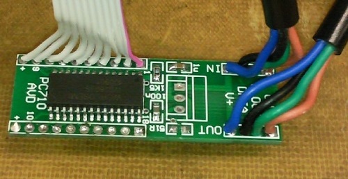
Back in mid 2011, I designed a small board that contained a switch-mode regulator (OKI-78SR-5/1.5-W36-C), a World Semi WS2803 LED driver and a few passives.
Power input can be in the range of 9V – 30V DC with no change in LED intensity.
The WS2803 chip (datasheet Download) has pixel style I/O (clock and data), but doesn’t use the same pass-through mode as the other pixel chips like the WS2801.
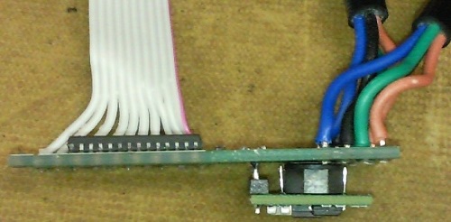
One mistake I made was the orientation of the regulator. I designed it to stand up, but that made it an awkward fit inside the candy cane tube.
For this board, I bent the pins back and soldered it to the underside. Not ideal, but usable.
The next revision of the board was to have the regulator laying down on the top side.
At the time, I didn’t get around to making more than the prototype candy cane. I was looking for a less time consuming way to wire up the LEDs and keep the wiring thin enough to not cause a shadow in the tube.
Dan Blickensderfer (Ohio Lights) on the other hand showed me the wiring jig he made. Unfortunately I moved onto other ideas and let the project languish in a box somewhere.
Update (Jan 2014)
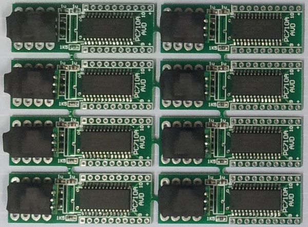
Here’s 8 of the updated PCB design (PC710A) with all parts mounted.
The regulator lays along the top now.
After the parts were loaded, they were snapped out of the panel and the edge spurs ground off.
I’m keen to make up 8 candy canes for my 2014 display and will add a page for them when done.
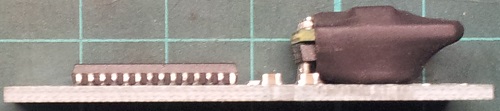
Side view of the revised board.
This version should fit in the canes better.
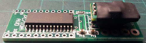
The input and loop (output) cables will go into the top of the board and be soldered on the bottom side.
All of the LED wiring will also go into the top of the board and be soldered on the bottom side.