2014 saw the introduction of 2-wire LED sets. These are still “2 channel” in the sense that the included controller can independently light up one set of LEDs or the other.
Previous 2 channel light sets were 3-wire; a common +ve wire and a separate -ve wire for each of the 2 channels.
These light strings can’t be used with conventional DC controllers.
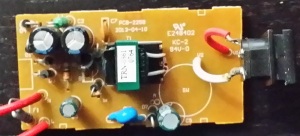
 Here’s the top side of the PSU / MFC combo PCB.
It uses a tiny switch-mode power supply to provide an isolated 31V DC.
The components and general construction look reasonable.
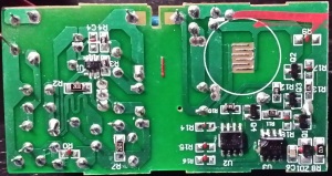
 Here’s the bottom side of the PSU / MFC combo PCB.
There’s a good amount of clearance between the mains and ELV sides.
The IC on the right is an Atmel 24C02B EEPROM, which most likely has the pattern data.
The one on its left is marked JT010B which would be a small microcontroller.
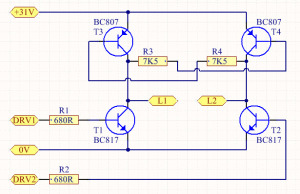
 Here’s a schematic of the MFC’s output driver.
It’s a discrete H-bridge employing bipolar transistors.
L1 and L2 are the output to the 2-wire LED string.
DRV1 and DRV2 are fed from the microcontroller.
Fellow ACL member Koolantz (Anthony) put his oscilloscope on the output of the controller to show the waveform.
The 2-wire LED strings seem to be available in a couple of different versions.

This one uses bi-colour LEDs. All LEDs light up one colour when power is applied one way and a different colour when power is applied with reversed polarity.
The wiring on this string is not confirmed, only guessed based on the 2nd version below.

This one uses regular LEDs. Every other LED lights up when power is applied one way and the other LEDs light up when power is applied with reversed polarity.
I could not find any current limiting resistors in this string.
Since all 10 sections are wired in series, you can’t cut them up and still use them on the same voltage.