This cheap and cheerful disco light was a whole $17.99 on eBay and is surprisingly bright.. They seem to have gone up to about $23 now, but that’s still a good price.
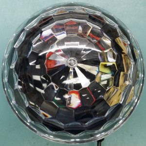 The 185mm plastic dome does quite a good job of creating a wide pattern of colour dots for your amusement.
Unsurprisingly, the focal point for the faceted dome is the centre level with its base where the LEDs sit.
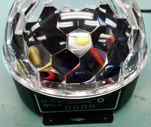 This shot shows how each facet is a lens.
That’s one small LED you can see in the centre of shot.
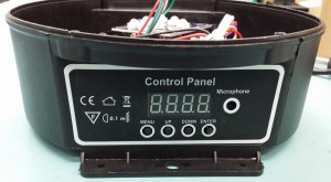 A few buttons and a 7-segment display are used for setting the mode and presumably the DMX address.
The manual (link way below) should spell it all out.
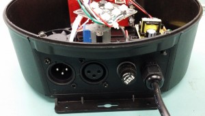 XLR connectors for DMX in/thru as well as a mains fuse and cable entry.
I haven’t tested the DMX control yet.
The fuse holder is the slightly dangerous types where you can come into contact with 240Vac when accessing it. Remember kids; always unplug before unscrewing the fuse cap!
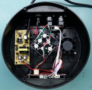 A small fan sucks out air. The inlet is under the power supply board.
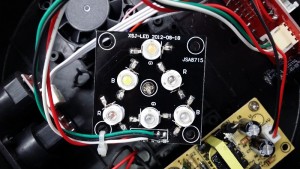 There are 6 LEDs on a board that it affixed to the shaft of a stepper motor.
The LEDs are wired in series pairs: Red + Orange, Green + Pink/Purple, Blue + White.
You can probably swap out some LEDs to make it RGB only.
I’ve since seen others on eBay that seem to use pairs of red, green and blue LEDs.
I did remove one of the 1W LEDs to see if the centre pad was soldered down, but luckily only the 2 tabs are.
This should make replacing the LEDs fairly easy. Some fiddling with the current limit resistors on the main PCB may be required though.
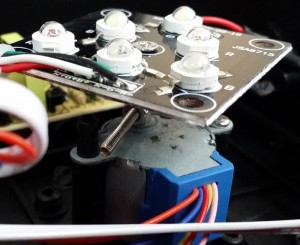 The stepper homes itself at power-up by running backwards and letting the extended shaft bolt hit a post.
This is the same homing method used by most DJ lights.
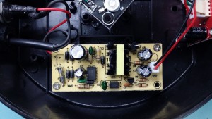 The power supply board looks half reasonable. The output of the power supply was measured as 12.7V DC while running.
One oddity it that the red wire is 0V and the black wire is +ve. Take that into account if you mod this light for an external 12V power input.
When fed from a 12V bench power supply, the current drawn was about 750mA maximum. I’d allow 1A to be safe.
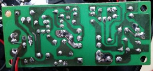 Plenty of clearance between the mains and low voltage tracks.
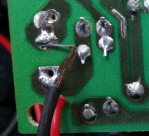
The black (neutral) wire is stripped back so far it’s almost touching the solder pads for the red one (active).
I fixed the dodgy mains wires after this photo was taken.
Scan of the “manual”: MXS-SJQS01_manual
