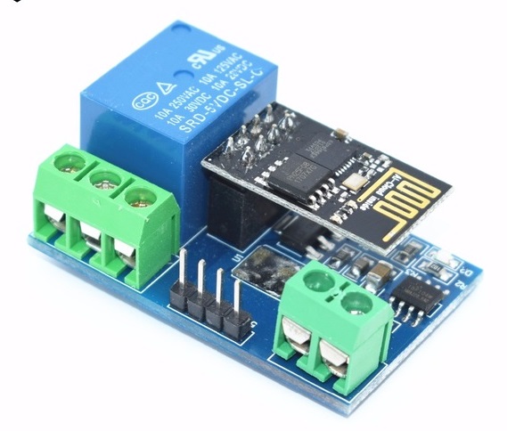
These relay boards can be bought on eBay. The one I got was marked HW-655. They use an ESP-01 (ESP8266) wi-fi module to control the relay. The original way to control the relay is by using serial commands:
- Open: 0xA0, 0x01, 0x00, 0xA1
- Close: 0xA0, 0x01, 0x01, 0xA2
They also need need configuration via the serial 4 pin header. Then the ESP-01 board sends those commands to the 8-pin micro which controls the relay.
With suitable code, the ESP-01 module could control the relay directly.
- Remove the 8-pin micro-controller.
- Link pin 3 (GPIO2) of the ESP-01 module to pin 7 of the (now empty) micro-controller.
- The ESP-01 can now activate the relay by setting GPIO2 high.
Another option is to run the Tasmota firmware on the ESP-01 module and configure it as per this page on GitHub. I’ve copied the relevant details below:
- Set module to Generic (in module configuration and click save)
- Set i.e. GPIO12 as Relay1 (in module configuration and click save)
- Disable seriallog (type
seriallog 0in the tasmota console) - Enable rules (type
rule1 1in the tasmota console) - Add the following rules typing in the console:
Rule1 on System#Boot do Baudrate 9600 endon on Power1#State=1 do SerialSend5 A00101A2 endon on Power1#State=0 do SerialSend5 A00100A1 endon
Then you can control it the same way as the Sonoff devices.
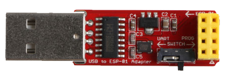
Use one of these USB adapters to program the ESP-01.
- Fit the ESP-01 module (covering most of the adapter)
- Set the switch to the PROG position
- Plug the USB end into your computer
- Move the switch to the UART position
- Upload the Tasmota firmware (see this page)
- Unplug USB and move the ESP-01 to the relay board